11n Beacon frame analysis using Wireshark
We have already discussed about basic 11bg Beacon frame structure in another post. Before proceeding for this post it’s recommended to go through 11bgBeacon post.
In this article we will try to see what are the fields are added in Beacon for 11n support and the meaning of each fields.
♣ Extra fields for 11n Beacon:
♦ “Tag: HT Capabilities (802.11n D1.10)”
Here is the picture for sub elements of HT Capabilities.

Now we can follow this screenshot for explanation of first three elements.
1. Element ID:
The element ID of “HT Capabilities” is 45.This is a fix number.
2. Length:
The length of HT capabilities is set to 26.
3. HT Capabilities Info field:

♠ HT LDPC coding capability: Low Density parity check code is one type of advanced error correcting code. This field indicates if the transmitter is capable of receiving any frame which is using LDPC.
♠ HT Support channel width: Sender supports 20MHz only or
40MHz (which means 20/40MHz). There is no 40MHz only.
♠ HT SM Power Save: Spatial Multiplexing Power Save is a new PS introduced in 802.11n. This is not widely used in actual devices.
♠ HT Green Field: This field indicates if transmitter is able to receive PPDUs with Green Field (GF) preamble or not. This is pure 802.11n frame which cannot be understood by 11bga (Legacy) devices.
♠ HT Short GI for 20MHz: SGI support for 20Mhz. Example: If device supports till MCS7 then and this bit is 1 (SGI supported for 20MHz), then the highest data rate is 72.2Mbps. If this bit is 0 (SGI is not supported for 20MHz), then the highest data rate is 65Mbps. Check MCS index table for better understanding.
♠ HT Short GI for 40MHz: SGI support for 40MHz.
♠ HT Tx STBC: Is transmitter capable of transmitting frame using STBC technology?
♠ HT Rx STBC: Is transmitter capable of receiving frame which is using STBC technology?
♠ HT Delayed Block ACK: Transmitter capability of supporting HT-Delayed BlockAck. We have rarely seen it as 1.
♠ HT Max A-MSDU length: Maximum A-MSDU frame is sent by this device.
♠ HT DSSS/CCK mode in 40MHz: Sender capability of using DSSS/CCK in 40 MHz.
♠ HT PSMP Support: Another new PowerSave in 802.11n but again not widely used.
♠ HT Forty MHz Intolerant: As there are only 3 (Considering support of Channel 1-11) non-interfering channels (1, 6 and 11) in 2.4GHz band. And if we use 40MHz as channel width then it’s quite congested for all devices to operate in 2.4GHz band in same vicinity. This option indicates if 40MHz + 2.4GHz is acceptable or prohibitive.
♠ HT L-SIG TXOP Protection support: This is another new type of protection mechanism introduced in 802.11n.
4. A-MPDU Parameters field:
Below is the diagram of A-MPDU subfields.

♠ Maximum Rx A-MPDU Length: Maximum size of Rx A-MPDU frame.
♠ MPDU Density: Minimum time between the start of adjacent MPDUs within an A-MPDU. Now this device is capable of processing any received A-MPDU where MPDU density is >= mentioned MPDU Density here. Suppose MPDU density is set to 4 μs [See sniffer capture for table], then MPDU density of received A-MPDU should be 4 μs/ 8 μs/ 16 μs.
5. Supported MCS Set field:

♠ Rx Supported Modulation and Coding Scheme Set: Rx Modulation and Coding Scheme (One bit per modulation): 1 spatial stream
…. …. …. …. …. …. 1111 1111 = Rx Bitmask Bits 0-7: 0xff
…. …. …. …. 0000 0000 …. …. = Rx Bitmask Bits 8-15: 0x00
…. …. 0000 0000 …. …. …. …. = Rx Bitmask Bits 16-23: 0x00
0000 0000 …. …. …. …. …. …. = Rx Bitmask Bits 24-31: 0x00
…. …. …. …. …. …. …. …0 = Rx Bitmask Bit 32: 0x0
…. …. …. …. …. …. .000 000. = Rx Bitmask Bits 33-38: 0x00
…. …. …0 0000 0000 0000 0… …. = Rx Bitmask Bits 39-52: 0x0000
…0 0000 0000 0000 0000 0000 000. …. = Rx Bitmask Bits 53-76: 0x000000
Only 0-7[MCS0-MCS7] are all 1 so this device is 1×1 or 1 spatial stream.
For example if the device supports 3 spatial stream then these fields look like below
Rx Modulation and Coding Scheme (One bit per modulation): 3 spatial streams
…. …. …. …. …. …. 1111 1111 = Rx Bitmask Bits 0-7: 0xff
…. …. …. …. 1111 1111 …. …. = Rx Bitmask Bits 8-15: 0xff
…. …. 1111 1111 …. …. …. …. = Rx Bitmask Bits 16-23: 0xff
0000 0000 …. …. …. …. …. …. = Rx Bitmask Bits 24-31: 0x00
…. …. …. …. …. …. …. …0 = Rx Bitmask Bit 32: 0x0
…. …. …. …. …. …. .000 000. = Rx Bitmask Bits 33-38: 0x00
…. …. …0 0000 0000 0000 0… …. = Rx Bitmask Bits 39-52: 0x0000
…0 0000 0000 0000 0000 0000 000. …. = Rx Bitmask Bits 53-76: 0x000000
We need to understand MCS Index table for better understanding. We will discuss in another post.
♠ Highest Supported Data Rate: This means, the highest data rate
that this device is able to receive, in unit of 1Mb/s. But we have seen this field is not used and set to 0 in maximum scenario.
♠ Tx Supported MCS Set: Just like Rx MCS Set, this fields indicates TX MCS Set for the device.
♠ Tx and Rx MCS Set: This field indicates if Tx MCS Set = Rx MCS Set. Most of the cases both are equal.
♠ Maximum Number of Tx Spatial Streams Supported: Self-explanatory.
♠ Unequal Modulation: If the device supports unequal modulation. This method is not widely implemented in 802.11n. MCS33-MCS76 was there to support this Unequal Modulation.
We can follow below table to understand the meaning of above 4 fields [All these fields set 0 for maximum scenarios] together.

6. HT Extended Capabilities:
Here is the structure
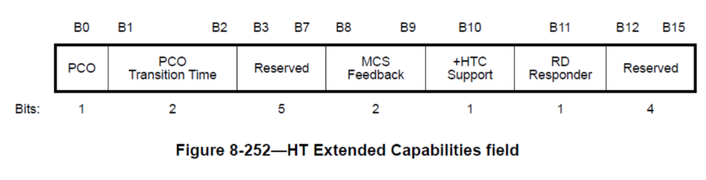
♠ Transmitter supports PCO: Indicates if AP support BSS as PCO BSS.
♠ Time needed to transition between 20MHz and 40MHz: If above field is 0, then this field is reserved.
♠ MCS Feedback capability: If AP is capable of MCS feedback mechanism.
♠ High Throughput: If AP supports +HTC or not.
♠ Reverse Direction Responder: If AP supports or not.
Screenshot for explanation

8. Transmit Beam Forming (TxBF) Capabilities:
Most of the 11n device does not support TxBF. Hence we see all fields are 0. We will try to understand TxBF in details in TxBF post.

9. Antenna Selection (ASEL) Capabilities:
Here also all fields are 0. Not supported or implemented in most of the 11n device.

♦ “Tag: HT Information (802.11n D1.10)”:
Here is the structure

♠ Tag Number: Tag number for HT information: 61.
♠ Tag length: Tag length for HT information: 22.
♠ Primary Channel: Primary channel of AP: 44.
1. HT Information Subset (1 of 3):
♠ Secondary channel offset: This indicates the offset of the secondary channel relative to the primary channel.
♠ Supported channel width: Current supported channel width.
♠ Reduced Interframe Spacing (RIFS): Indicates of RIFS is permitted or not in BSS.
♠ Reserved: ☻
2. HT Information Subset (2 of 3):
♠ HT Protection: Current protection mechanism is used in BSS.
♠ Non-greenfield STAs present: Indicates if all associated STAs are greenfield capable or not.
♠ Reserved: ☻
♠ OBSS non-HT STAs present: Use of protection for non-HT STAs by overlapping BSSs is needed or not needed
♠ Channel Center Frequency Segment 2: I do not know.
♠ Reserved: ☻
3. HT Information Subset (3 of 3):
♠ Reserved:
♠ Dual beacon: Indicates if AP transmits STBC beacon or not.
♠ Dual Clear To Send (CTS) protection: Support of dual CTS for protection in BSS.
♠ Beacon ID: Indicates that “Is it a primary beacon or STBC beacon?”
♠ L-SIG TXOP Protection Full Support: Indicates “One or more HT STAs in the BSS support or do not support L-SIG TXOP protection”.
♠ Phased Coexistence Operation (PCO): Is PCO used in BSS? We have seen that PCO was not supported by AP. So, obviously this will be 0 here also.
♠ Phased Coexistence Operation (PCO) Phase: Reserved as PCO is not active.
♠ Reserved: ☻

4. Rx Supported Modulation and Coding Scheme Set:
This indicates the MCS set used for current BSS.

♣ When there is HT capabilities then why do we need HT information field?
First of all HT capabilities is for advertising AP’s maximum capabilities through Beacon. Example: AP may be capable of 2×2 40MHz.
Now, HT information is to show current status of BSS. Example: If one 1×1 20MHz supported STA connects to AP, then we should see 1×1 20MHz information inside HT information instead of 2×2 40MHz information.
This gives another point is, HT information field’s value may change depending on current connected STAs capabilities. But “HT capabilities” is fixed until we change any configuration of AP. If we observe carefully, we can see fields present inside HT information are changeable. Example: HT protection, Non-Green Field station present, OBSS non-STAs present, Channel width etc.
Here is one example for “non-green field STA present”

Note: WMM is mandatory for 11n. We will discuss in another post for WMM.
♣ Conclusion:
From above analysis we can get to know about AP’s capabilities and also current BSS status.
This AP is 802.11n with below important parameter settings
| Band | 5Ghz |
| Channel | 44 |
| Channel width | 40MHz |
| Spatial Stream | 1×1 |
| TxBF | Not supported |
| SGI | Supported maximum for 40MHz |
| Max Rx A-MPDU | 16383 Bytes |
| Max Rx A-MSDU | 3839 Bytes |
♥♥If you have any doubts or query please let me know in comment section or send mail at feedback@wifisharks.com.♥♥
Sushma
when we configure AP as 40MHz channel width. The primary channel is 6 then what will be the secondary channel.
Bamdeb
If primary channel is 6 then secondary channel may be 2 or 10.