How to get AID from TIM field (Using Partial Virtual Bitmap – PVB)?

Before we proceed for this article you should know about powersave mechanisms.
As we know, in powersave mechanism wireless client wakes up to see Beacon’s TIM field if there is any data buffered for this client’s AID. Now, how client gets the AID from TIM field? If there are multiple clients connected to AP and AP has buffered data for multiple clients then how all AIDs are indicated inside TIM fields? In this article we will learn about the calculation of AID from TIM fields.
♣ What is AID? More details on AID.
AID = Association identifier. On successful association AP assigns one unique + integer number [1, 2, 3, 4, ….2007] to client and sends the AID in Association Response frame.
♦ AID field structure:
| ♠INFO♠ | ♠VALUE♠ | ♠EXTRA MEANING♠ |
| AID field size | 2 Octets | 16bits |
| AID range | 1-2007 | Theoretically max 2007 clients per AP |
| 1-2007 LSB or MSB? | Placed in 14 LSBs of 2Octets | Little-Endian |
| What about 2 MSBs? | 2 MSBs are set to 1 | 14bits for AID and rest 2bits are set to 1. |
♦ AID from Association Response frame:
We can see below sniffer capture screenshot and explanation
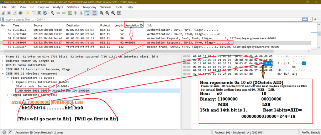
AID is 16 and it’s represented like below.
| 1 | 1 | 0 | 0 | 0 | 0 | 0 | 0 | 0 | 0 | 0 | 1 | 0 | 0 | 0 | 0 |
| Bit15 | Bit14 | Bit13 | Bit12 | Bit11 | Bit10 | Bit9 | Bit8 | Bit7 | Bit6 | Bit5 | Bit4 | Bit3 | Bit2 | Bit1 | Bit0 |
MSB LBS
Note:
1. IEEE LMSC uses Little-endian notations in its standard. So, we assume 802.11 data represents in little-endian. We keep bit0 at left side for easy understanding; otherwise this whole concept will be confusing.
2. We have observed below bit representation in IEEE 2012 spec for any field structure. Style is Left to right.
Bit0 Bit1 Bit2….Bitn
3. In this article we have examples and explanations where MultiBSSID is False.
♣ What is the use of AID 0?
We have never seen AID 0 is given to any client, the AID assignment start from 1. Why?
Keeping MSB 14, 15 as 1, 1 and rest of all as 0 means AID=0.
| 1 | 1 | 0 | 0 | 0 | 0 | 0 | 0 | 0 | 0 | 0 | 0 | 0 | 0 | 0 | 0 |
| Bit15 | Bit14 | Bit13 | Bit12 | Bit11 | Bit10 | Bit9 | Bit8 | Bit7 | Bit6 | Bit5 | Bit4 | Bit3 | Bit2 | Bit1 | Bit0 |
♦ This combination is Reserved.
♦ Bit Map Control is 1 octet field and its Bit0 indicates the traffic associated with AID 0. And we know this bit indicates about Broadcast/Multicast traffic buffered at AP. So, it’s virtually assigned for AID 0 .There may be some use of this inside code, I am not sure about it.
♣ Fact about AID 2007/2008/16383:
AID 2007 can be represented as below in binary
| 1 | 1 | 0 | 0 | 0 | 1 | 1 | 1 | 1 | 1 | 0 | 1 | 0 | 1 | 1 | 1 |
| Bit15 | Bit14 | Bit13 | Bit12 | Bit11 | Bit10 | Bit9 | Bit8 | Bit7 | Bit6 | Bit5 | Bit4 | Bit3 | Bit2 | Bit1 | Bit0 |
As we can see total 11 Bits [Bit0 to Bit10] are enough to represent 2007. Including the 3 most significant zero to make it fit inside 14Bits [Bit0 to Bit13].
Now, next number of 2007 is 2008 and max number for 14bits LSB is 16383.
Values 2008 to 16383 are reserved [Bit14 and Bit15 are 1].
16383 means [Ignore Bit14 and Bit15]
| 1 | 1 | 1 | 1 | 1 | 1 | 1 | 1 | 1 | 1 | 1 | 1 | 1 | 1 | 1 | 1 |
| Bit15 | Bit14 | Bit13 | Bit12 | Bit11 | Bit10 | Bit9 | Bit8 | Bit7 | Bit6 | Bit5 | Bit4 | Bit3 | Bit2 | Bit1 | Bit0 |
♣ What is the use of Bit Map Control field?
Bit Map control is 1 Octet.
| 0 | 0 | 0 | 0 | 0 | 0 | 0 | 0 |
| Bit7 | Bit6 | Bit5 | Bit4 | Bit3 | Bit2 | Bit1 | Bit0 |
Bit0 [Multicast Bit]: Used for indicating of Broadcast or Multicast data.
Bit1-Bit7: This is called Bitmap Offset. This field helps to save spaces for Partial Virtual Bitmap (PVB). Slowly we will come to know how?
Now, if 1 is to all Bit1 to Bit7, then we get 127 as decimal value. Keep this in mind. So the range is 0-127.
Mainly, Bitmap Offset value helps to jump on to specific Byte of PVB and then see further to calculate AID.
♣ What is Partial Virtual Bitmap (PVB)? How to extract AID?
PVB is 251 Octets in size (Max). Each bit represents the AID of connect stations for which AP has unicast buffered (if that AID bit=1) data.
251 Octets = 251*8 = 2008bits [This is same as max AID value. AID 0-2007]
♠ Scenario1:
Suppose Bit1 of PVB is 1 and all rest of the bits are 0, then PVB will be 1 octet. So, PVB will not be 251 octets always. PVB size will be reduced depending on scenarios. We will understand more when we will see more scenarios. Here, as Bit1 is 1 so no need to send rest of the bits as 0 in the air. It’s waste of space. Bit1 is 1 means, AP has buffer data for station AID 1.
Now, Bitmap Offset subfield is 0 and TIM tag length is 4.
TIM Tag Length 4 Octets = DTIM count [1 octet] + DTIM period [1 octet] + Bitmap control [1 octet] + PVB [this scenario 1 octet]
♠ Scenario 2:
Suppose there are 80 clients connected to AP and there is not buffer data for AID 1-70.But there is buffer data for AID > 70. Then all those bit are 0 for 1-70 AID in PVB. No need to send those 0 in air. Here Bitmap Offset helps to indicates how bits are 0 in PVB so that we can skip and jump to actual byte of PVB.
Example: Bitmap Offset is N. So, 2 x N bytes are set to 0 in PVB.
***Let’s try to understand some line from 802.11 2012 IEEE spec.
“When dot11MgmtOptionMultiBSSIDActivated is false, the Partial Virtual Bitmap field consists of octets numbered N1 to N2 of the traffic indication virtual bitmap, where N1 is the largest even number such that
bits numbered 1 to (N1*8) – 1 in the bitmap are all 0 and N2 is the smallest number such that bits numbered
(N2 + 1)*8 to 2007 in the bitmap are all 0. In this case, the Bitmap Offset subfield value contains the
number N1/2, and the Length field is set to (N2 – N1) + 4.”
$Example to understand the above statements$
We have
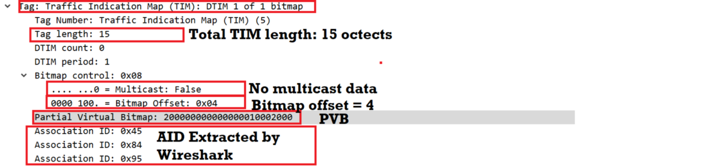
1. TIM Length: 15 octets.
2. Multicast bit = 0 [Not useful for our calculation as it’s a separate 1 bit field]
3. Bitmap offset = 4 [Decimal]
| 0 | 0 | 0 | 0 | 1 | 0 | 0 | 1 |
| Bit7 | Bit6 | Bit5 | Bit4 | Bit3 | Bit2 | Bit1 | Bit0 |
Bitmap Control Field [Bit0 for multicast and rest of the Bits are for Bitmap offset]
4. PVB = 0x 200000000000000010002000 [Hex Value]
So,
PVB length = Total Length – DTIM count -DTIM period – Bitmap Control = (15 – 1 – 1 – 1 ) Octets = 12 Octets [Look, actual PVB is 251 octets but here 12 octets are used or enough to indicate powersave clients’ AID]
From, IEEE statement:
a) MultiBSSID is False [Because rules are different if MultiBSSID is True. Just remember in general or our normal usage cases, MultiBSSID is False].
b) “Partial Virtual Bitmap field consists of octets numbered N1 to N2 of the traffic indication virtual bitmap,”
N1 and N2 are the octets numbered range where we can see some bits are 1 to indicate any particular AID for sleeping station.
Now, We know Bitmap offset is 4 .This indicates 4*2 = 8 Octets = 64 bits are filled with 0. So, actual PVB starts on 8th [Count from 0] Octet and ends at (8+12)-1th octets = 19th octets.
So N1 = 8, N2 = 19
Let’s see PVB bits structure.
| 0 | 0 | 0 | 0 | 1 | 0 | 0 | 0 | Byte-0 |
| Bit7 | Bit6 | Bit5 | Bit4 | Bit3 | Bit2 | Bit1 | Bit0 |
.
.
.
| 0 | 0 | 0 | 0 | 0 | 0 | 0 | 0 | Byte-7 |
| Bit63 | Bit62 | Bit61 | Bit60 | Bit59 | Bit58 | Bit57 | Bit56 |
Byte-0 to Byte-7 (Total 8 bytes) all bits are 0.
c) “where N1 is the largest even number such that bits numbered 1 to (N1* 8) – 1 in the bitmap are all 0”.
1 to (N1*8) – 1 = 1 to (8*8) – 1 = 1 to 63bits in the bitmap are all 0. This is true.
With Bitmap offset indication the above 8 bytes will not be part of PVB, so PVB is reduced to 12 bytes. Useful Bits are from Bit64 to Bit159.
Let’s fill Byte-8 to Byte-19 according to PVB hex number after converting to binary.
PVB (Hex) = 0x200000000000000010002000 [Shown in Wireshark] = Read each octets in reserve order and got [Refer first screenshot of this article]
0x00 20 00 10 00 00 00 00 00 00 00 20 [12 octets]
| 0x | 00 | 20 | 00 | 10 | 00 | 00 | 00 | 00 | 00 | 00 | 00 | 20 | Read right to left |
| Binary | 8 Zeros | 00100000 | 8 Zeros | 00010000 | 8 Zeros | 8 Zeros | 8 Zeros | 8 Zeros | 8 Zeros | 8 Zeros | 8 Zeros | 00100000 |
| 0 | 0 | 1 | 0 | 0 | 0 | 0 | 0 | Byte-8 |
| Bit71 | Bit70 | Bit69 | Bit68 | Bit67 | Bit66 | Bit65 | Bit64 | |
| 0 | 0 | 0 | 0 | 0 | 0 | 0 | 0 | Byte-9 |
| Bit79 | Bit78 | Bit77 | Bit76 | Bit75 | Bit74 | Bit73 | Bit72 | |
| 0 | 0 | 0 | 0 | 0 | 0 | 0 | 0 | Byte-10 |
| Bit87 | Bit86 | Bit85 | Bit84 | Bit83 | Bit82 | Bit81 | Bit80 | |
| 0 | 0 | 0 | 0 | 0 | 0 | 0 | 0 | Byte-11 |
| Bit95 | Bit94 | Bit93 | Bit92 | Bit91 | Bit90 | Bit89 | Bit88 | |
| 0 | 0 | 0 | 0 | 0 | 0 | 0 | 0 | Byte-12 |
| Bit103 | Bit102 | Bit101 | Bit100 | Bit99 | Bit98 | Bit97 | Bit96 | |
| 0 | 0 | 0 | 0 | 0 | 0 | 0 | 0 | Byte-13 |
| Bit111 | Bit110 | Bit109 | Bit108 | Bit107 | Bit106 | Bit105 | Bit104 | |
| 0 | 0 | 0 | 0 | 0 | 0 | 0 | 0 | Byte-14 |
| Bit119 | Bit118 | Bit117 | Bit116 | Bit115 | Bit114 | Bit113 | Bit112 | |
| 0 | 0 | 0 | 0 | 0 | 0 | 0 | 0 | Byte-15 |
| Bit127 | Bit126 | Bit125 | Bit124 | Bit123 | Bit122 | Bit121 | Bit120 | |
| 0 | 0 | 0 | 1 | 0 | 0 | 0 | 0 | Byte-16 |
| Bit135 | Bit134 | Bit133 | Bit132 | Bit131 | Bit130 | Bit129 | Bit128 | |
| 0 | 0 | 0 | 0 | 0 | 0 | 0 | 0 | Byte-17 |
| Bit143 | Bit142 | Bit141 | Bit140 | Bit139 | Bit138 | Bit137 | Bit136 | |
| 0 | 0 | 1 | 0 | 0 | 0 | 0 | 0 | Byte-18 |
| Bit151 | Bit150 | Bit149 | Bit148 | Bit147 | Bit146 | Bit145 | Bit144 | |
| 0 | 0 | 0 | 0 | 0 | 0 | 0 | 0 | Byte-19 |
| Bit159 | Bit158 | Bit157 | Bit156 | Bit155 | Bit154 | Bit153 | Bit152 |
From above PVB representation, we get AID: 69(0x45), 132(0x84) and 149(0x95). Now we can see the previous Wireshark screenshot to match the AIDs, extracted by Wireshark in Hex.
From Byte-20 to Bytes-251 all bits are 0. This part will not be sent as part of PVB.
| 0 | 0 | 1 | 0 | 0 | 0 | 0 | 0 | Byte-20 |
| Bit167 | Bit166 | Bit165 | Bit164 | Bit163 | Bit162 | Bit161 | Bit160 | |
| 0 | 0 | 0 | 0 | 0 | 0 | 0 | 0 | Byte-21 |
| Bit175 | Bit174 | Bit173 | Bit172 | Bit171 | Bit170 | Bit169 | Bit168 |
.
.
d) “and N2 is the smallest number such that bits numbered (N2 + 1) * 8 to 2007 in the bitmap are all 0.”
(N2+1)*8 to 2007 = (19+1)*8 to 2007 = Bit160 to Bit2007 in the bitmap are all 0.
e) ” In this case, the Bitmap Offset subfield value contains the
number N1/2, and the Length field is set to (N2 – N1) + 4.”
Bitmap offset value = N1/2 = 8/2 = 4 and TIM length = ( N2 – N1 ) + 4 = ( 19 – 8 ) + 4 = 15.
♣ Let’s try some more examples to get AID:
Practice 1:
We are given this information

1. Length = 4
2. Bitmap offset = 1
3. PVB = 0x 01
Sol:
Now, as per Bitmap offset we should skip 1*2=2Bytes=2*8Bits=16Bits as these are filled with 0.
PVB length = 4 – 3 = 1 octet.
So PVB has bit16 to bit23 which means AID 16 to AID 23.
PVB = 0x 01 = 0000 0001 in binary.
| 0 | 0 | 0 | 0 | 0 | 0 | 0 | 1 |
| Bit23 | Bit22 | Bit21 | Bit20 | Bit19 | Bit18 | Bit17 | Bit16 |
So, this Beacon indicates buffer data for AID = 16.

Practice 2:

PVB length = 7-3=4 Bytes
Bitmap offset = 0,
So, 0*2=0 this means no skipping of bytes in PVB.
PVB = 0x 02 00 00 00 => [Reverse Bytes] 0x 00 00 00 02
PVB in binary:
| 0 | 0 | 0 | 0 | 0 | 0 | 1 | 0 |
| Bit7 | Bit6 | Bit5 | Bit4 | Bit3 | Bit2 | Bit1 | Bit0 |
| 0 | 0 | 0 | 0 | 0 | 0 | 0 | 0 |
| Bit15 | Bit14 | Bit13 | Bit12 | Bit11 | Bit10 | Bit9 | Bit8 |
| 0 | 0 | 0 | 0 | 0 | 0 | 0 | 0 |
| Bit23 | Bit22 | Bit21 | Bit20 | Bit19 | Bit18 | Bit17 | Bit16 |
| 0 | 0 | 0 | 0 | 0 | 0 | 0 | 0 |
| Bit31 | Bit30 | Bit29 | Bit28 | Bit27 | Bit26 | Bit25 | Bit24 |
So, AP has buffered data for AID 1 which is same mentioned by Wireshark.
But I am not sure why AP used 4 Bytes of PVB where 1 Byte is enough to indicate AID 1. This is a random capture. This may be implementation dependent or there were other clients connected to AP.
Below is the commonly used parameter to indicate AID 1.

Practice 3:

PVB length = 4-3=1 Octet.
Bitmap Offset = 0. So, start from 1st Byte of PVB.
PVB = 0x 04 = 0000 0100 = Bit2 is 1 so AID is 2.
♣ Get AID for below samples:
a.

b.

c.

♣ Conclusion:
I hope we have learned the logic and calculation to get AID. One point is, we do not see PVB as 1 as this means PVB indicates unicast data buffered for AID 0. But there is no client of AID 0. We have already discussed about AID 0.
Leo Fenner
Hi,
In the first example PVB is from 8th octet to 19th octet. So, in PVB bytes 0 to 7 are all zero and bytes 20 to 251 are all zero
8th octet starts at bit 57 and ends at bit 64, you have started from bit 64. Why?
Bamdeb
Hi Leo,
I have to go through this concept again and get back to you. Keep reading..
Thanks.
GUNA
regarding DTIM, let`s assume 5 station is associated with one AP . The 5th station listen interval is 5 milli sec. but only station 5 going to sleep. during sleep ap buffered multicast frame. AP transmitted multicast frame to first 4 stations that time 5th station is sleeping. then AP buffered frame for station 5 which indicates in DTIM bitmap control field. In multicast frames AID is 0. then once station 5 wake up and then AP will transmit multicast buffered frame that only received by only 5th station or every 5(4 awake already receive + 5th station sleep to awake) station again receive?
Bamdeb
Hi GUNA,
Let me understand and correct some of your statements.
[regarding DTIM, let`s assume 5 station is associated with one AP . The 5th station listen interval is 5 milli sec. but only station 5 going to sleep. during sleep ap buffered multicast frame]
—-> This is fine. Understood.
[AP transmitted multicast frame to first 4 stations that time 5th station is sleeping]
—-> AP can not send multicast data to some station.
In AP there is one DTIM period is set . suppose DTIM period is 3.This means
1st beacon DTIM count is 2
2nd beacon DTIM count is1
3rd beacon DTIM count is 0 [This is DTIM beacon. After this beacon AP will broadcast it’s buffered multicast data no matter what STA is awake or sleeping.] AP does not case as there is no ACK in multicast/broadcast Data.
If you can read this https://wifisharks.com/2020/10/10/dtim-delivery-traffic-indication-map/
Then you will get clear idea about DTIM.
[then AP buffered frame for station 5 which indicates in DTIM bitmap control field. In multicast frames AID is 0. then once station 5 wake up and then AP will transmit multicast buffered frame that only received by only 5th station or every 5(4 awake already receive + 5th station sleep to awake) station again receive? ]
—> some TIM and DTIM concept got mixed up. Please read https://wifisharks.com/2020/10/10/dtim-delivery-traffic-indication-map/
and if you any doubt ask.
Thanks.
Althaf
Please explain about
multiple bssid TIM IE encoding ,
both method A and method B
Bamdeb
Hi Althaf,
Till now, I do not have knowledge on Multi BSSID TIM.
Thanks
HARSHA
SUPER EXPLATION SIR!!